I recently decided to build myself a racing quadcopter. I’ve never flown a remote controlled aircraft of any sort, so I was starting from a point of almost complete ignorance. It took quite a bit of chasing rabbits down many holes, but after considerable internet exploration I managed to find everything required to get a four-propeller bird into the air.
Following is a parts list, which I’ve just ordered, that should be complete enough to get flying. In the future I’ll no doubt extend this to include such things as FPV (First Person View) equipment, but for now I’ll just be happy if I can get off the ground.
Parts:
- Transmitter and Receiver
- Frame
- Flight Controller (CC3D)
- ESC (Electronic Speed Control)
- Motors (brushless)
- Propellers – 2xCW 2xCCW (one pair clockwise, one pair counter-clockwise)
- Power Distribution Board (PDB)
- Battery Connector
- LiPo Battery
- LiPo Battery Balancing Charger
Most kits available will have some of these parts, but generally not all. For example I bought all the parts from eBay and Deal Extreme, including a kit that contained all except the transmitter, receiver, and battery related items. So in most cases some knowledge of how these parts work together is required in order to know which ones to get.
Transmitter and Receiver
The transmitter (controller) typically comes with a receiver when purchased. The transmitter sends a signal over a number of channels, each channel being responsible for controlling one component of the quadcopter (e.g. controlling the throttle or pitch). So you’ll need at least 4 channels: throttle, pitch, roll, and yaw. It is often recommended to have 6 channels so that other features can be added to your quad later on. The transmitter typically sends its signal over a 2.4GHz band, the receiver receives the signal, breaks it up into the channels, and then sends each channel to the flight controller.
Flight Controller (CC3D)
The flight controller is the brains of the operation. It receives signals to move the aircraft and based on gyroscopic and acceleration sensors it decides what its orientation is and how best to implement your command by adjusting the power to each motor. The flight controller sends commands to the motors via electronic speed controllers.
ESC (Electronic Speed Control)
The ESCs drive the brushless motors by sending pulses along three lines. They receive their commands from the flight controller along a signal line (which actually has three cables – more on this in a moment), and they receive their power directly from the battery.
Each signal line is paired with two power lines (red and black). I found this confusing at first since the ESCs are powered by another two lines (also red and black) which are thicker and clearly the only ones capable of carrying enough current to drive the motors. So what are the other two, thinner power lines for? As it turns out, even though they are paired with the signal lines they are nothing to do with them and in fact provide power to the flight controller from the Battery Elimination Circuit (BEC). So then my question was, “what is the BEC?” Well, it’s a DC-DC converter/regulator and each ESC is equipped with one. I’m not sure why they call them BECs instead of voltage regulator or similar, and I’m not sure why they equip the ESCs with them rather than having them separate. One side effect of having them in the ESCs is that you end up with four when you only need one. Most instructions suggest removing the red line from three of them leaving only one to connect to the flight controller.
One more thing to consider with ESCs is the firmware. SimonK seems to be one of the most common, BLHeli too – both are open source. When purchasing ESCs they will have the firmware already flashed, so this isn’t really something I’ll want to worry about until I get somewhat more serious and significantly more skilled. I have read that the BLHeli firmware is more responsive, but I doubt I’d be able to tell the difference.
Motors (brushless)
Three phase brushless motors are driven from the three outputs of the ESC. The flight controller tells the ESCs how fast to spin each motor, the ESCs then figure out how to pulse the three magnetic poles within the motors to drive them accordingly. These little motors are very impressive and can change speed with incredible acceleration. The motors I’ve order are 2280kv. This means that they should spin at 2280RPM (revs per minute) per volt with no load – again, a theoretical value, don’t ever use the motors with any power without a load. More info here.
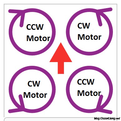
Propellers – 2xCW 2xCCW (one pair clockwise, one pair counter-clockwise)
Typically plastic propellers are used. Don’t be fooled, they can pack a punch. I’ve been told I should search youtube for “quad propeller injury” as a warning against carelessness. Carbon fibre props are also available, however these may not be a good idea since they are harder to break, meaning any crashed are likely to transfer any damaging force to the motors and arms.
Props are described by their radial length (length from the centre to the tip) and their pitch. The props I’m using are 5030, meaning they are 5 inches and have a pitch of 30 degrees. A larger pitch pushes more air, but also draws more current and creates more turbulence.
The last thing to know about the props is that you have two spinning clockwise and two spinning counter-clockwise. More information here.
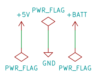
Power Distribution Board (PDB)
Power distribution boards (typically a printed circuit board – PCB) come in many shapes and sizes. Their purpose is to make connecting the battery, ESCs, flight controller and other devices more convenient.
The power distribution board that comes with the kit I ordered is as simple as possible – it simply gives a few convenient solder points for the battery and ESC power terminals. I plan to upgrade in the near future to one that replaces one entire layer of the frame with a circuit board and includes a 12V regulator for use with FPV gear. This will significantly reduce the potential rats nest of wires required to connect everything together.
Battery Connector
There are a number of battery connectors used by LiPo batteries and you must make sure you have the right connector or adapter so that you can plug your battery into your PDB. A list of some of the more common connectors can be found here (scroll most of the way down the very long page). You’ll also have to make sure your charger has a compatible connector or adapter. My battery and kit both come with T plugs (Deans Ultra), so I’ve bough a banana plug to Deans Ultra cable for charging.
LiPo Battery
There is a lot to learn about LiPos. In particular they are scarily powerful. The maximum rate of power that can be discharged is measured as a factor of the capacity. The capacity is measured in amp hours (Ah) or milliamp hours (mAh). So for example, the batteries I’ve ordered have an 1800mAh capacity. This means that if I run them at 1.8A they will theoretically last one hour. The discharge rate of the battery is called its C rating, for the batteries I ordered they are 30C, which means they can discharge at 30 times the capacity, which is 30×1.8 = 54A. That’s a lot of current! It is a theoretical value and I don’t know how close you can actually get to this in reality, but that aside, they are still very powerful batteries and can do a lot of damage – search YouTube for LiPo battery explosions. There is also a C rating for the charge rate of the battery. This will tell you the current you can pump into your battery while charging.
Finally different LiPos have different voltages. This is because they have different numbers of cells in series and each cell is 3.7V. The batteries I ordered are 3S, meaning 3 cells in series, and are therefore 11.1V.
A very thorough explanation of LiPo batteries, connectors and chargers can be found here.
LiPo Battery Balancing Charger
You’ll need a charger that is specifically designed for charging LiPo batteries. The easiest and most common are the so called 4 button chargers. They can charge a wide range of devices. Many of them do not come with a power supply so you’ll have to acquire one separately in most cases. An old PC power supply should work fine, just make sure you check its maximum current rating for its 12V connection and don’t ask for more than it can give.
A thorough explanation of chargers can be found here.
Frame
I’m not sure what the pros and cons of the various frame sizes and configurations are, except that they are typically fibreglass or carbon fibre. Carbon fibre is only slightly more expensive and should be lighter and stronger. The frame I’ve ordered is the ZMR250, which is very similar to the popular QAV250. The 250 refers to the diagonal length (approximately) which is 250mm.